3 minutes | magazine 01/2020
Simply explained: Load sensing system
Load sensing is a term familiar to anybody who works with mobile cranes. But what does it actually mean?

Jörg Gebele, Group Leader Hydraulic Design, Liebherr-Werk Ehingen GmbH
Jörg Gebele explains
Jörg Gebele, Hydraulic Designer at Liebherr in Ehingen, gives us a brief insight into hydraulic systems and explains this smart system.
Every machine contains a drive unit whose power is transferred to one or more power units. On our mobile cranes, in crane mode the power generated by the diesel engine is transferred to the various crane units by the hydraulic system, in other words to the hoist unit, the slewing unit and the luffing and telescoping units. The hydraulic system has the task of distributing the power to the crane units as energy-efficiently as possible. None of the units must run too quickly or too slowly.
The hydraulic system must supply the perfect level of power for each individual crane system.
Furthermore, the hydraulic pressure must be high enough to ensure that none of the units stops. Hydraulic systems in various forms can be used for this purpose. One of them is the so-called “load sensing” hydraulic system.
Load sensing simply means feeling the load or, in other words, the load pressure. It is often abbreviated to ‘LS system’. A hydraulic pump with an adjustable delivery volume is used in the LS system. The maximum operating pressure is reported to the pump’s controller by all the crane units through a chain of non-return valves. This is known as the ‘LS pressure’. The controller adjusts the delivery rate of the pump so that it delivers precisely the correct hydraulic pressure and precisely the correct delivery volume to achieve the speeds required by the operator. This satisfies the main objective of not generating excess hydraulic energy which then simply has to be throttled back. The LS system is therefore also a major help in reducing fuel consumption.
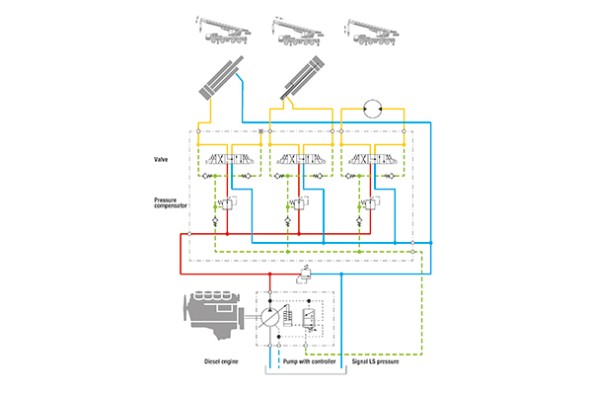
However, if there is more than one crane unit being actuated, there is another difficulty. Unless additional precautions are taken in the LS system, the majority of the oil from the pump would be discharged through the path of least resistance to the crane unit with the lowest operating pressure. This crane unit would then operate excessively quickly whilst the unit with the highest load pressure could initially actually stop. The speeds of the various systems would then affect each other. However, that is not what the crane operator has set the crane to do and is undesirable.
To ensure that the speeds are as required by the operator, an additional hydraulic element must be positioned upstream of each valve – a so-called pressure compensating valve. By closing as the pump pressure increases and opening as the pump pressure falls, this compensates pressure differences like a scale and prevents any of the crane units having a negative effect on any of the others.
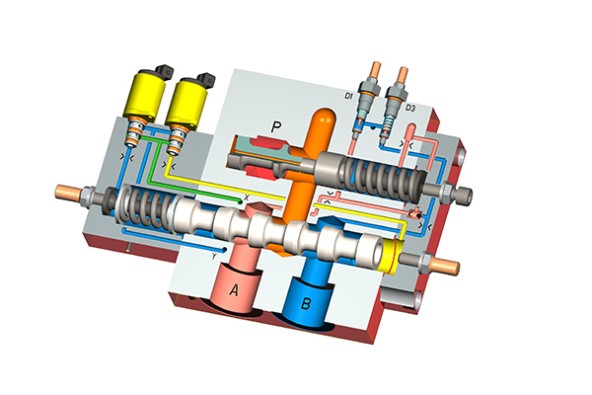
3-D section drawing of a load sensing valve with a pressure compensater
There are various types of LS systems. For example, the LS pressure is signalled in our cranes using pressure sensors by electricity and not by hydraulics, as was the case in the past. This means that it is an electrical, not a hydraulic LS system. Furthermore, in addition to the “closed centre” LS system with an adjustment pump described above, there are also “open centre” LS systems with a constant pump and a pressure compensating valve with an additional tank connector through which the surplus oil can be discharged. As a consumer, the slewing unit often takes the form of an open centre LS system. Moreover, not only can the pressure compensating valves be installed upstream of the valves, but also downstream of them.
This article was published in the UpLoad magazine 01 | 2020.

