3 minutes | magazine 02/2019
Simply explained: The finite element method
Tobias Haller, a structural engineer at the Liebherr Plant in Ehingen, explains the term “finite element method (FEM)”.

Tobias Haller
The importance of the finite element method:
“The FEM is extraordinarily important to us. If we did not have it, the lightweight construction that we use for our cranes would be inconceivable. We would not be able to supply our customers with cranes which have high lifting capacities on the one hand whilst being economical to drive on roads on the other.
Our daily bread in structural engineering is the question as to how much the material is stressed by external forces. The stresses on geometrically simple forms, such as a bar or cuboid, can be calculated using well-known physical formulae. But how can more complex forms be calculated if there are no formulae for them? And this is precisely where the finite element method comes in.
The FEM enables us to evaluate lots of different design ideas without having to physically build them. This, in turn, enables us to develop new solutions more quickly and bring them to the market.
The body you wish to calculate is broken down into a finite number of parts with a simple form. In other words, for example, into lots of small cuboids or tetrahedrons. These are the “finite elements”. The physical properties of each individual small element, such as the relationship between force and deformation or between heat and temperature, can be described by mathematical equations. This means that complicated forms can be calculated using lots of small bodies. Although this results in a large number of linear equations, fortunately they can be solved efficiently using modern computers.
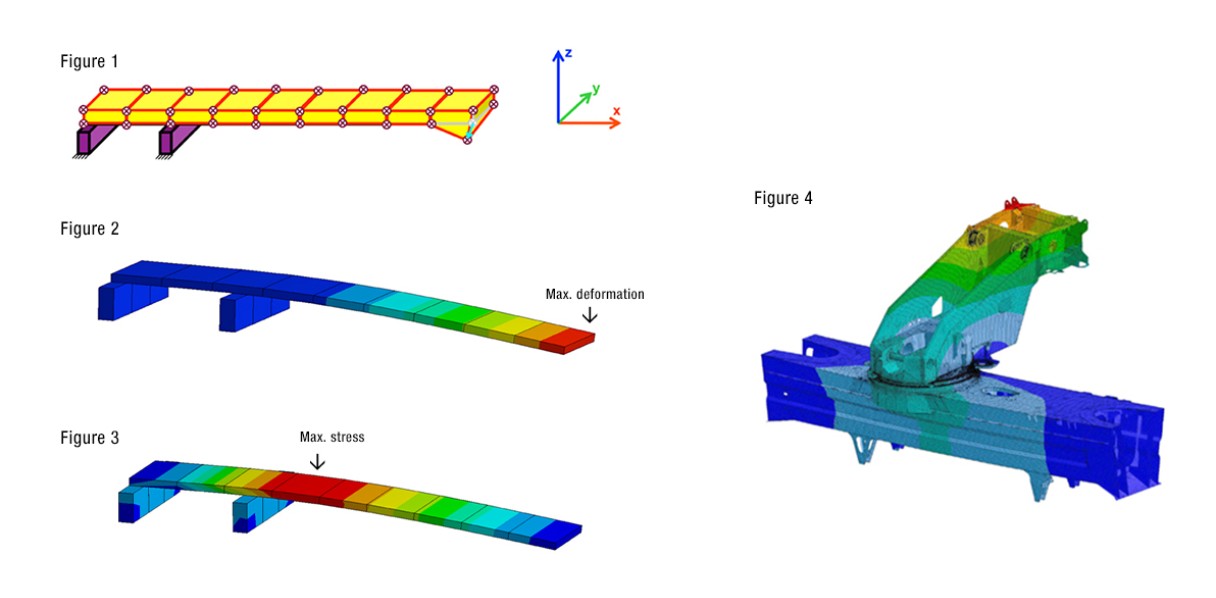
Let’s take a look at a simple example (see Figure 1): A long narrow body is divided into nine finite elements. This results in 40 junction points which join the elements. Each junction point may be deformed by stresses in three spatial directions, x, y and z. This means that we have a total of 40 x 3 = 120 unknown deformations. To solve this, we require 120 linear equations. Figure 2 shows the deformations resulting after solving the equation system, whilst Figure 3 shows the stresses derived from the deformations in the body. The rule of thumb for both diagrams is that the redder the colour, the greater the stress. When we complete the calculations for our cranes, we obviously have significantly more finite elements to contend with, and therefore millions of equations. The more elements we have, the more precise the result will be. Nevertheless, FEM is still only an approximation method. Figure 4 shows the FEM evaluation relating to the deformation slewing platform on a vehicle frame.
FEM enables us to evaluate lots of different design ideas without having to physically build them. This, in turn, enables us to develop new solutions more quickly and bring them to the market.”

This article was published in the UpLoad magazine 02 | 2019.


